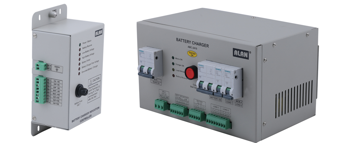
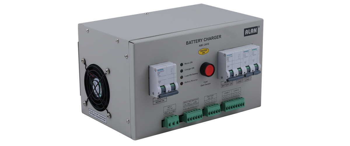
Introduction : RMU battery charger (24V) is specially design for switch gear unit. It provides power to switch gear motor without any interruption. The system gets operating supply from Charger 1, Charger 2 and Battery. Both the Charger Outputs are combined through a suitably rated Blocking Diode. This final output is given to the Battery as well as for Load through the Controller Card. If there is any failure in Charger 1, Charger 2 will take care of Battery Charging process and the Entire Load. During Mains Failure/ Failure in Both the Chargers, Battery will take care of Entire Load. So Failure in any One/Two Power sources (Charger 1, Charger 2 & Battery), the alternate source will take all the Load, and also ensures Bumpless switching between the sources.
This system consists of mainly three parts. They are :
1. Redundant Battery Chargers.
2. 24V Battery.
3. Controller Card.
TECHNICAL SPECIFICATIONS :
- 1.Battery Voltage: 24 VDC
- 2.Battery Capacity: 12 Ah at 20 hour discharge rate
- 3.Battery Charger Module Rating: 10A continuous per charger (Two 5A Power Supplies are connected in parallel)
- 4.Battery Charging Type: CC, CV
- 5.Battery Charger Cooling: Natural Air with air ventilation louvers on metal enclosure.
- 6.Battery Charger O/P Regulation: +/- 2%.
- 7.Battery Charger Output Ripple: 1% rms.
- 8.AC Input Power: 170 to 285 VAC, 1 Phase, 50 Hz. +/- 5%
- 9.Built in Charger Protections :
a) Output Over Load.
b) Output Short Circuit.
c) Input Over Voltage (above 320V RMS for short duration) - 10. Visual Indications: a) MCU Faulty
b) Charger 1 Fail
c) Charger 2 Fail
d) Battery Low/Battery Reverse
e) Mains On - 11.Input Short Circuit Level: 10 KA
- 12.Input Side Insulation Withstand : 1500 VAC for 1 minute.
- 13.Input Side Insulation Resistance: 10M. Minimum measured with 500 VDC Megger.
- 14.Cable Termination: Pluggable type, to accommodate up to 2.5 mm² wire.
- 15.Remote Indication Relay: a) Battery Low/MCU Faulty (Potential Free Contact)
b) Charger 1 Fail (Potential Free Contact)
c) Charger 2 Fail (Potential Free Contact).
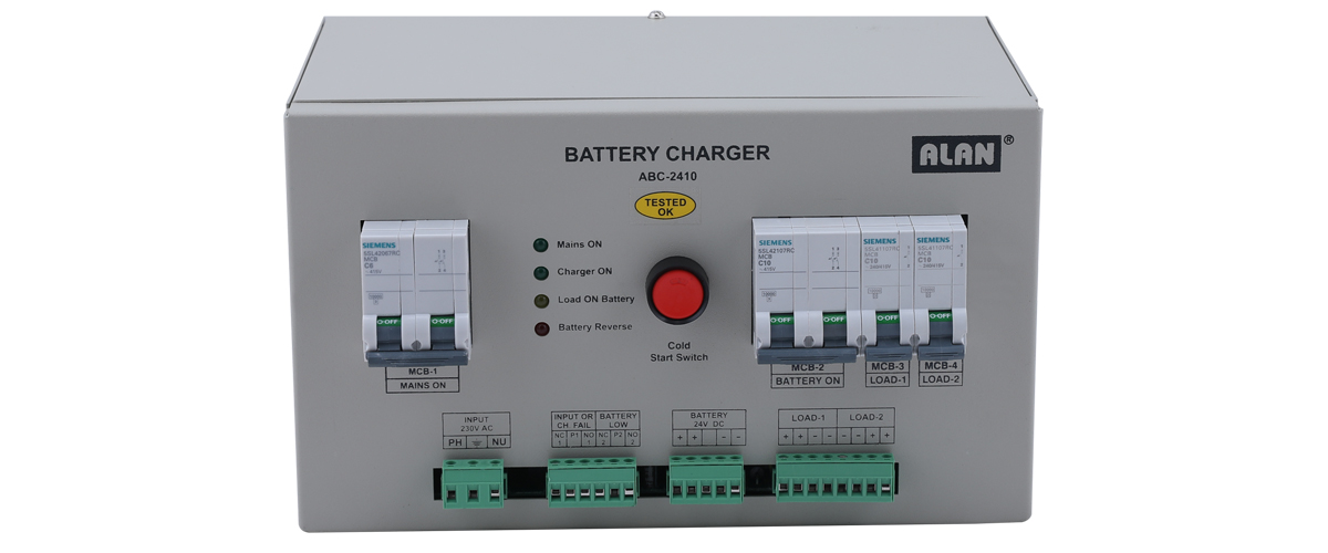
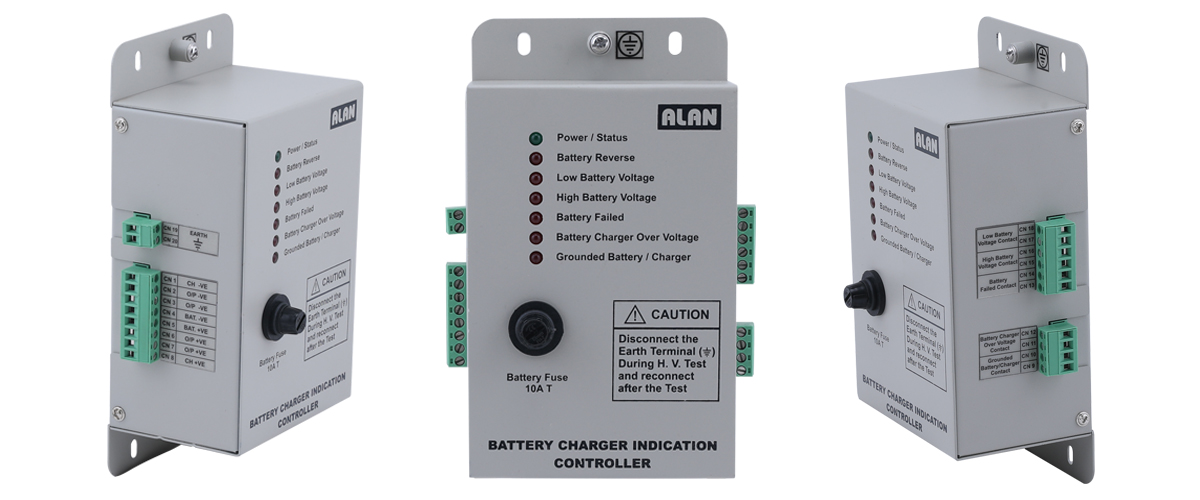
VISUAL INDICATION :
There are 6 Visuals Indication.
Visual Indication Descriptions:
- 1. MCU Faulty (Red Led): This will blink whenever the control section malfunctions or controller gets hang.
- 2. Charger 1 Fail (Red Led): This will glow whenever the Charger 1 output fails/falls below its threshold level.
- 3. Charger 2 Fail (Red Led): This will glow whenever the Charger 2 Output Fails/Falls below its threshold level.
- 4. Battery Low/Battery Reverse (Red Led): This will glow whenever the Battery Voltage falls below the threshold level/Battery is been disconnected/Battery is been connected in reverse way. During Battery reverse condition, Battery reverse indication in Controller Card will also glow.
- 5. Main ON (Green Led): This will glow as long as AC input to the system is present.
- 6. Battery Reverse (Red Led): This will glow in Controller Card whenever Battery connection is reverse.